Civil 3D 2012 is live

Just a quickie to let you know that Civil 3D 2012 is now live for you subscription users. It is quite hefty at 3.4Gb to download.

As always, your best bet for downloading it via the Download Manager. I cannot tell you how many times this has saved me from re-downloading because of a network glitch.

But enjoy the new release. There will be more stuff forthcoming from SimplyCivil3D.

Alignment Tangency

One of the cool features of Civil 3D 2012 is the ability to force tangency on an alignment. This can occur if you are starting an alignment from lines/polylines and the sections are not quite tangent with each other.

When you create the alignment from these entities, by default a warning symbol will appear over the section where it is not tangent with the other entity.

This can be turned on or off from the Alignment Properties found on the Alignment tab and Modify panel. Or you can simply right-click on the alignment and select Alignment Properties. The Alignment Properties dialog will open. It is the Design Criteria tab that you are interested in.

When you take a look at the alignment, a little more in-depth by looking at the Geometry Editor (Alignment tab, Modify panel) and then selecting the Alignment Grid View tool, you can see the alignment tangency problems a little clearer.

By clicking on one of the Tangency Constraints that are highlighted as not being tangent, you can see some new options.

For the purposes of our exercise, we want to make the lines/curves all tangent to each other. So we will select the Constrained on Both Sides (Free) option.

You can see instantly, that the arc section has been modified so that tangency is created. The warning symbol disappears. Do this for all constraints which are not constrained. Further, you can (of course) modify the curve radius for each curve section.

So, you can see the finished alignment. The new alignment tools in Civil 3D 2012 are indeed powerful.

AutoComplete – Tip

While this is not really a Civil 3D-specific command, it is one that is found in AutoCAD 2012. Some people may hate the new functionality that now shows an auto-complete box  every time you start typing something on the keyboard from a command line.

Here is what it looks like out of the box. This is with Dynamic Input Turned off.

And this is with Dynamic Input turned on.

You can totally turn that functionality off by either typing AUTOCOMPLETE OFF. Or you can right-click on the auto-complete dialog and unchecking Selection List.

Now the auto-complete is turned off, or not visible any more.

Just a few pointers about this new functionality though that you MIGHT like:

  • There is an option to Auto-Append.  This will allow the command to filled in. This might be especially useful if you are looking for the tool to turn off the geo marker. By typing in GEOM with auto-append on, it will fill out the rest of the command (GEOMARKERVISIBILITY).
  • The Suggestion List turns the flyout list on or off as was demonstrated earlier.
  • Display Icons turns the little icons to the left of the command on or off. In my opinion, if you want the suggestion list turned on, turn OFF the icons as its just a little more graphics overhead.
  • Display System Variables is very handy to have turned on. It will display any system variables along with commands in the suggestion list.
  • Delay time will set the time before the box appears. The default is 0.30 seconds. You *could* set it for longer if you wanted to zip along doing whatever and then for those commands that are longer to type in, it will start displaying the suggestion box.

So, there you have it. This tip is just for your edification on this new functionality.

Calculate Volume from 2 Profiles

Someone on the discussion group asked about how they can get a volume between 2 Profiles. In their case, they have dirt and rock and need to figure out the amount of rock that needs to be removed.

Here is my answer. There may be others, but this is what popped into my head first:

Here is a profile showing an Existing and Proposed surface. For this case, will say the existing (red line) is the dirt and the proposed (blue line) is the rock.

Go back to your plan and sample the alignment from which the profile was derived:

  1. From the Home tab and Profile & Section Views panel, select Sample Lines. The Create Sample Line Group dialog box opens.
  2. In the Create Sample Line Group dialog, select the two surfaces and then click OK.
  3. In the Sample Line Tools and Sample Line Creation Methods drop-down, select By Range of Stations.
  4. In the Create Sample Lines dialog, change the Sampling Increments to whatever you want to sample. In my case, I’m going to sample every 2′ for Tangents/Curves/Spirals. Click OK.

Now we need to assign materials for those two surfaces.

  1. In the Analyze tab and Volumes and Tables panel, select Compute Materials. In the Select a Sample Line Group, make sure your alignment and Sample Line Group is selected, then press OK.
  2. The Compute Materials dialog box opens. To keep it simple, I’m going to click the for the EG and Datum to EG and FG respectively. Click OK.

We’re almost there! Now lets create a table showing the cumulative volumes.

  1. Still in the Analyze tab and Volume and Materials panel, select Total Volume Table. Select the criteria you want to display, place the tables on your drawing and – done.

You can see on the table that it maintains a running cumulative cut/fill volume tally. So to see the whole result, look at the last section.

In reality, you did not have to sample that close, but it shows what’s happening so you can better analyze what’s going on.

If you have a better way to approach this, please comment so I (and others) can learn.

Net/Gross Areas – A Quick Tip

As I decided to take a nap after dinner, I awoke and am now wide awake. I find that the quiet hours of the morning is when my brain starts whirring and thinking of things.

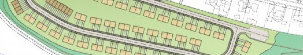
So, I pass along this little tip. I think I am in the minority when I start talking about Net/Gross area computation as it pertains to parcels. Here in our neck of the woods, certain municipalities require the parcel to be calculated from the center of the road back to the rear of the lot (Gross Area). Their reasoning is that tthe homeowner is then responsible for all maintenance of their property; including any road, curb, sidewalk, or utility maintenance. Pretty sneaky, eh?

But the municipality also needs to show the actual usable building area. This is typically calculated from the right-of-way back to the rear of the lot (Net area).

So, how does one lay something like this out in Civil 3D and make it look like it supposed to be; with no lines on top of lines? The answer, my friends is sites.

Here is our workflow for this situation:

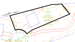
  1. Create parcels based upon the Gross area on a site called Gross.

  1. Create parcels based upon the Net area on a site called Net.

The Net parcel style is simply a dot pattern with dots spread out very far, and the color of the parcel is very faint. We Do not want to show the acutal Net parcel lines on our drawing, we just need it for area calculation purposes.

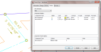
We have 2 labels set up; one to calculate the Gross area on the Gross site, and one to calculate the Net area on the Net site.

Now, to go off on a tangent a bit – I could have sworn that earlier version of Civil 3D allowed one to create a label using data from multiple sites. I’m thinking Civil 3D 2010. But I’m at home and don’t have access to that. Civil 3D 2012 doesn’t allow this any more, so I am left to create 2 labels and sort of add them together to make them visually look like one label.

If you don’t use Net/Gross areas, perhaps you can use this same methodology for something else. I know its a workaround, but it works for us. If you have any other ways that would streamline this process, I’d love to hear it.

Civil 3D 2012 – Level of Detail

One of the real nice things with Civil 3D 2012 is the addition of a level of detail tool. How many times have you had a huge surface and made the fatal mistake of trying to perform an object view? Either it crashed on you, or you wait… and wait… and wait.

The Level of Detail Tool Found on the View tab and views panel will help with that.

This surface is set with contours of 1′ and 5′ intervals.

It consists of the following data:

  • 11,275,000 sq. feet
  • elevation ranges from 547 to 842
  • 393,664 points
  • 785,127 triangles

So it is kind of large.

Clicking on the Level of Detail tool will bring up this dialog box. you can permanently disable that by clicking in the check box.

After some recalculating and regeneration, the surface now looks like this:

Wait! did it get rid of those contours? Nope, it just minimized the number of contours when you are zoomed out.

When you zoom in, you can see that your contours show up.

And when you perform an Object View, you will now see that you can move and rotate the surface – with ease!

Thumbs up – Autodesk!

Civil 3D 2012 New Pipe options – a perspective

For many years, people have complained about Civil 3D and the way they draw/calculateĀ  pipes and structures; that they go from center of structure to center of structure.

Their opinions have been valid. I have heard such things as:

  • Slopes CAN be incorrect if you are calculating the actual length of pipe (subtracting 4 feet from the pipe length). And if one is trying to hold a minimum slope, the actual will vary from the engineered calculations.
  • Pipes only go to the inside of the structure anyways.
  • And other issues.

Enter Civil 3D 2012 and it new capability to set the pipe based on:

  • Center (as it has been before)
  • Inside wall of structure
  • Outside wall of structure

Does this now change the game for pipes and how they will be used? It will quell the engineers who fought so long for true pipe slopes. It may help with the quantity takeoffs, but we all know that they buy pipe in set lengths and cut them in the field (at least they do for the small 8″ PVC pipes).

How will one differentiate on their plans that they are now using lengths from inside instead of center?

Does this muddy the waters? Is the new pipe options a “Godsend” or a curse now that we will have it once Civil 3D 2012 is released?

Let me hear your comments.

Poll – How soon will you upgrade to Civil 3D 2012?

It’s SOON here! What will you do with the new release?